|
Dear visitors. This is an article dedicated to SolidStructural - 3D Steel AutoDetailing software. I will try to tell you more about SolidStructural, explain the advantages and limitations of this program. This software is based on my 17 years of experience in AutoCAD, Design Data SDS/2 (since 1999) and programming skills (Visual Basic, MS Access and AutoLISP).
Alex Borodulin NYacad, Inc. President |
|
|
SolidStructural - 3D Steel Auto Detailing software running inside AutoCAD. The interface of the program is based on MS Access database. The user creates 3D model of structure and in auto regime drawings and reports. The changes made in database are reflected in the 3D model with the corresponding auto updating of drawings. SolidStructural is different from other 3D Steel programs. In its development the new solutions were implemented: non-graphical input, preliminary design of submaterials and others. The main advantages of SolidStructural:the program is easy for use and learning, predictable and effective. It is an affordable software for individual detailers and small companies.
Each 3D steel AutoDetailing program will offer you to work with a number of parameters describing details participating in connection (could be more than 60 for moment or other types of connections) + you have to assign additional parameters: distances, gaps, specify bolts etc. Everything in one place (beam or column edit form). Surely it is not easy to work with such a big number of parameters; often you have to make several attempts in order to get an appropriate design. |
|
|
In SolidStructural the user makes preliminary design of details using convenient forms with advanced graphical user interface and fast input. Play video: Clip Angles input Design of connections is based on selecting preliminary developed details and assigning parameters describing specific connection.
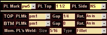
Input of shear (top three boxes in the picture above) and moment bolted connections. Play video
As you can see, the user makes just a few inputs to specify connection. In SolidStructural, when you - not the program - make the design of details (submaterials), the result is more predictable:
|
Clip Angles form (part): pictures are widely used in SolidStructural to help make user's input |
|
In SolidStructural the approach used by other 3D systems in assigning parameters for submaterials was revised to be more understandable. When you define shear plate detail, you are assuming that the horizontal distance to first hole is the distance from edge of plate. It makes sense. This is the way a shear plate is defined in SolidStructural. What does not make sense is when that distance is defined as a distance from the end of the beam. Each time when the distance from beam end to steel face is different (due to web thickness of supporting beam or setback varies) you will get the new shear plate design → extra submaterial mark → extra problems in fabrication. |
|
|
Often the design of structures is assuming the use of both light and heavy beams (e.g. W12x26 and W12x136). In this case using standard setback distance (the distance from the working point to the end of the beam) for all beams can cause too small gap between the beam end and the steel face (e.g. 1/4"). So you have to edit beam ends, calculate and assign new setbacks - that takes time. SolidStructural is using distance to steel face for defining standard clearance: the distance from the end of the beam to intersection of beam centerline and steel face. You always have predictable field clearance. This parameter is defined in 'Setup' form:
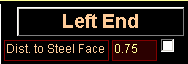
When you open 'Beam Edit' form, you can see this distance for left and right ends of beam:
The user can change the value of that parameter, make it User or Auto (calculated by the program). Solidstructural is designed to round beam length to 1/4" for all types of connections. |
|
 |
|
|
3D models produced by SolidStructural + plain AutoCAD
|
|
|
In SolidStructural there are several design and drafting solutions you can use on the constant base. These features either ignored by other systems or offered solutions cannot comply satisfactory with detailing requirements.
Two types of drawings should be done properly for this type of connection: shop drawings of beams and erection plans. You have to add the information about wall bearing ends on erection plans: plate mark, bearing elevation etc. All these tasks solved in Solidstructural: shop drawings and erection plans with all required information produced in Auto regime. Play video: Add Wall Bearing Connections
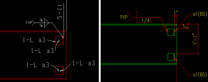
Wall bearing Anchors. Two types of drawings: AutoDetailing in SDS/2 (left picture) and in SolidStructural (right). No editing operations were performed in both versions.
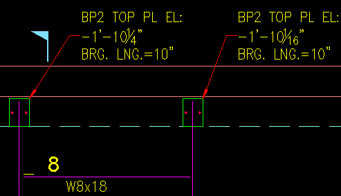
SolidStructural. Wall bearing beams on erection plan (Auto drafting)
|
|
|
SolidStructural gives at your disposal effective solutions for adding plank (deck) support angles. Play video: Add Plank (deck) Support Angles The picture ►represents the part of shop drawing produced by SolidStructural with plank support angles (no editing operations were performed).
|
 |
|
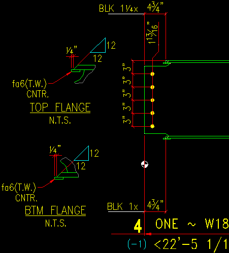
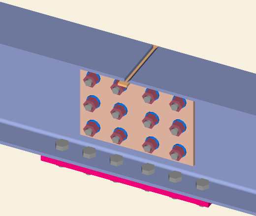
SolidStructural supports skewed moment (bolted and welded connections). Design of moment connections can be easily done in 'Beam Edit' form (no need to go to a 3D model, perform navigation, manually add plates, backing bars etc.). A lot of of efforts was made in achieving better performance of generated shop drawings. Play video: Add Moment Welded Connections
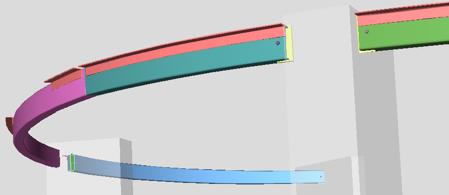
SolidStructural. 3D model: W18x35 beam, moment welded, framing conditions - skewed. |
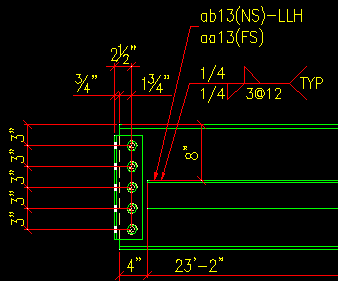
Solidstructural. Part of auto generated shop drawing
|
|
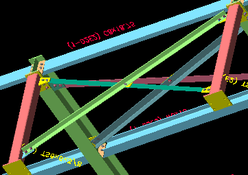
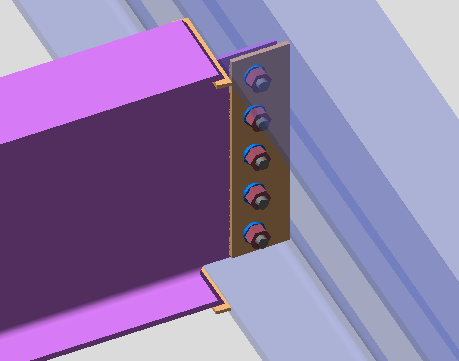
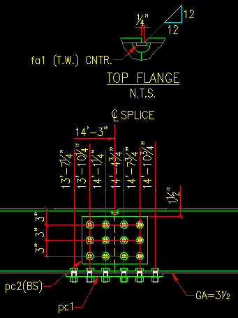
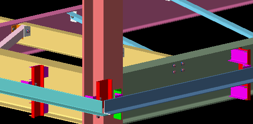
Typical task in renovation types of jobs: split long beam in 2 or more parts and make an assembly in the field. This type of connection is pretty tough:
Play video: Spliced Beam input
Solidstructural. 3D Model: Spliced Beam
|
Solidstructural. Spliced Beam detail (part of the drawing) |