
![]() Play
Movies:
Play
Movies:
|
|
| Create Structural Drawings within minutes! |
|
|
Contents:
1. Overview
2. Setup
5. Grid
6. Base Plates
7. Add Columns, Base Plates and Anchor Bolt Dim's (plan)
7a. Add Beams Normal to Elevation View (elevation)
8. Add Beams
10. Report
12. Registering
Quick Structural is MS Access application for creating ERECTION PLANS, ELEVATIONS, GRIDS and ANCHOR BOLT PLANS AND DETAILS in AutoCAD. System requirements: AutoCAD2000 and higher + MS Access2000 or higher.
After auto installation is complete new folder will be created on your PC:
C:\Quick Structural\
Open it and double click on the file Quick Structural.mde
Start AutoCAD and configure your support path information to include the directories
C:\Quick Structural\
and
C:\Quick Structural\Support
To do it type at the command prompt: preferences. In opened dialog window select Tab “Files”. Press button “Add…”, then “Browse…”, find folder C:\Quick Structural and double click on it. Repeat to include C:\Quick Structural\Support
Open ACAD template file C:\Quick Structural\QuickStructural.dwt. Set up layers’ colors accordingly to your standards. Do not change names of layers and text styles in this file.
Next include file QuickStructural.lsp in ACAD Startup Suite. To do it type at the command prompt: appload
Then press button “Contents…”.
![]()
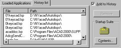
In the next window press button “Add…” and browse to find folder
C:\Quick Structural\Support
Click on the file QuickStructural.lsp in that folder.
Close all windows. Leave AutoCAD (do not close it!)
Now configure MS Access.
Open any existing database (*.mdb or *.mde file).
Go to menu
Tools
Options…
Click on “Keyboard” tab and set options as shown below:
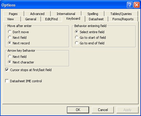
Press OK. Close MS Access.
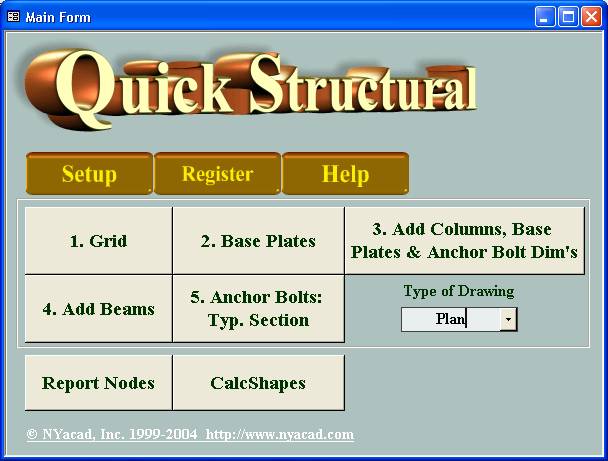
Copy into your current project’s folder the file Quick Structural.mde. Rename it (e.g.
First Floor.mde) and double click on it to start the program. Main form pops up (see picture below).
You can create plans for any number of floors (levels) of your project. After you finished work with the first floor you can copy database First Floor.mde, rename it (e.g. Second Floor.mde) and so on.
Default parameters can be assigned in form “Setting” (button “Setup” in main form).
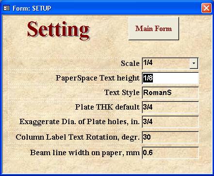
Here you can set:
Scale of the drawing
Text height and style
Default thickness of base plates
For better representation of plates on anchor bolt plan you can show enlarged holes. Specify the value of enlargement in the field ‘Exaggerate Dia. of Plate holes, in’.
Thickness of the lines representing beams on erection plan you can assign in ‘Beam line width on paper.’
In main form click on button 1.Grid. New form will appear.
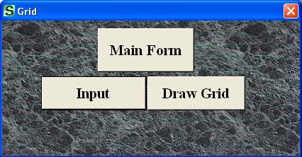
Click button “Input”. After that you can see on the screen 2 forms: “Grid: Vertical Lines” and “Grid: Horizontal Lines”. Enter names of grid lines and distances.
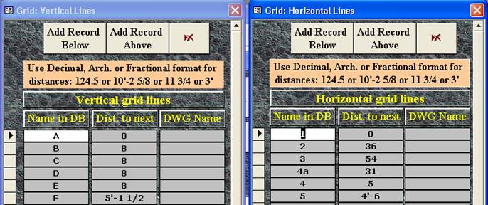
Example:
Type “A” in field “Name in DB”, press Enter, type “B”, press Enter and so on. Then you fill out distances between horizontal grid lines.
Remark: in both forms (“Vertical lines” and “Horizontal lines” first row in field “Dist. to next” must be 0 (zero).
In above picture (see form ‘Grid: Vertical Lines’) the distance 5’-1 ½ represents distance between “F” and “E” vertical grid lines.
Close forms (click on the cross on the right upper corner of the form). If you need to remove or add (in regard with cursor location) the grid line, then press the corresponding button. Example: you need to add new grid line B1 between A and B lines. Place cursor into the record B field ‘Name in DB’ (form ‘Grid: Vertical Lines’). Click on button ‘Add Record Above’. Type: B1. Next press Tab on keyboard. Type the distance from new line B1 to line A.
To delete record click on button ![]() .
.
Remarks: 1. In case you have already beams or columns in database be careful with renaming or deleting of grid lines in “Grid” forms, because it could destroy the database.
If you need to edit or delete grid lines’ names:
Edit grid lines (forms ‘Grid: Vertical lines’ and ‘Grid: Horizontal lines’).
Go to main ‘Draw grid’ form and draw grid in AutoCAD.
After that you have to go to form ‘Beams’ and edit nodes’ names (assign new values) and delete beams with nodes’ names you had deleted.
Repeat procedure in ‘Columns’ form.
Following this sequence of command will prevent you from severe error.
2. Try to avoid using in Database grid lines names like A.5 or G1.2 etc. Real names for grids as per your contract drawings could be assigned then (see the following paragraph)
3. If you edited or deleted records in Input grid forms (‘Grid: Vertical Lines’ and ‘Grid: Horizontal Lines’), you have to perform drafting of grid (see the following explanations).
Press button “Draw Grid” in small form “Grid”. In opened Main Grid form (see picture below) select scale, check lines you wish to be present in your drawing (use pairs of buttons for check-uncheck) and specify the name of drawing name for grid. Now you can assign real grid name in field “DWG Name”. After that press button “Draw Grid”. Additional options in form “Grid” – locking and unlocking of grid layers (the ones with name “Grid…”) can be used when you have “Grid” drawing as an active drawing. On Pressing button “Lock grid” you can get better conditions to continue development of your drawing (ACAD entities on locked layers cannot be affected by selection). If you need to edit grid, then press button “UNlock grid”. You also have an option what to show on drawing: database Grid name (option button “Show DB Name”) or contract drawings’ grid name (option “Show real name”). In current release you are able to draw the grid with grid lines bubbles located on both left and right or top and bottom sides.
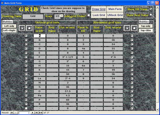
After grid is completed press button “Main Form”.
Remark: All grid items are placed on separate layers, so you can make any of them invisible by freezing (layers named “Grid…”).
Press button “2. Base Plates” in main form.
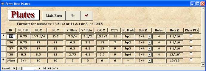
Fill out parameters of base plates. While working in this form read help string in the left lower corner of Access window.
You can specify plates with no holes (check field “Plain PL?”), one, two or four holes. Pictures below show location of the first hole:
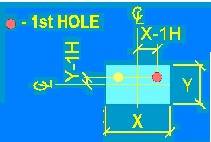
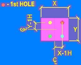
Locations of holes may be symmetrical or nonsymmetrical.
Remark: to facilitate input use the button “Duplicate Record” and TAB for moving to the next field.
Press button “3. Add Columns, Base Plates and Anchor Bolt Dim's” in main form (you have selected “Plan” in main form field “Type of drawing”). In opened form select scale, text style and PSpace Text Height (you can correct MSpace text height then).
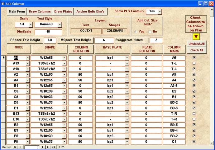
Fill out nodes and shapes (W, TS and Pipe shapes only) by selecting them from the lists. Check columns you are planning to show on plan. Assign column rotation, degrees (W-shape web or TS long wall horizontal = 0 degree, W-shape web or TS long wall vertical = 90 degrees). Press button “Draw Columns”. If you are working on erection plan, then close this form and open “4. Add beams” form. If you need to create anchor bolt plan, then press button “Add Plates”. You can suppress visibility of base plate’s contour by selecting “No” in combo box “Show PL's Contour?” To add anchor bolt dimension press the corresponding button.
Remarks:
1. 1. For better performance of your drawing you can exaggerate columns with plates. Put any number bigger then 1 in text box “Exaggerate, times”. Columns and plates will be scaled as per number you specified.
2. 2. Do not allow columns’ names duplication (e.g. if you have two columns A1, the program will produce an error).
If you have selected “Elevation” in main form field “Type of drawing”, click on button “Beams Normal to Elevation View”.
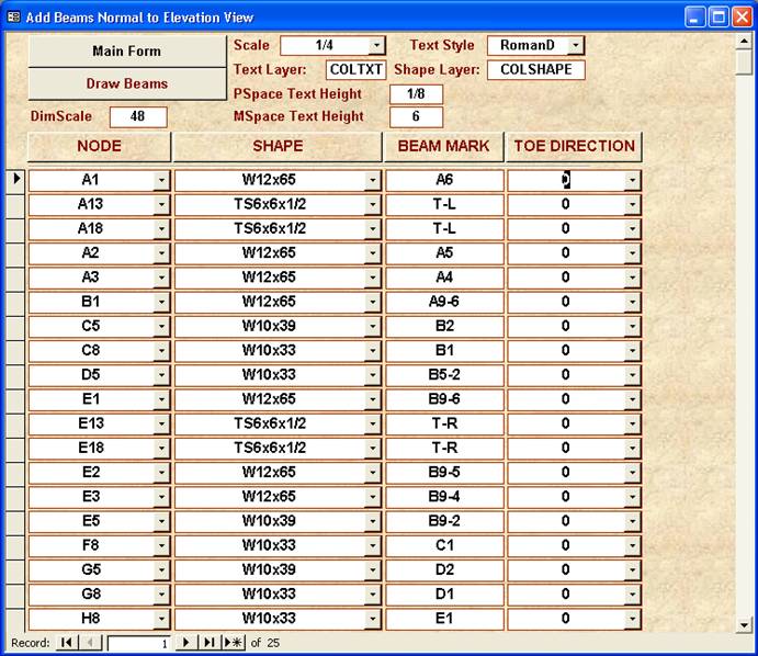
Enter node, select shape, assign beam piece mark and select toe direction. Click on button “Draw beams”
In main form press button “4. Add Beams”. Select scale, text style and PSpace Text Height (you can correct MSpace text height then). Fill out beam nodes, shapes, IDlayer and Toe direction (for C, MC and L-shapes only) by selecting them from the lists. If 1st and (or) 2nd end of beam are plain (e.g. wall bearing beam end) check boxes “1st End Plain?” and (or) “2nd End Plain?”. Select layer for beam (new or existing, visible or invisible), if you’d like to show different types of beams using different colors and LineTypes.
The button “Duplicate record” will help you to save time on input.
Press the button “Draw Beams”.
Remark: Do not allow beams’ names duplication (e.g. if you have two beams A1B1, the program will produce an error).
On pressing this button the new form for drafting of typical anchor bolt detail will show up.
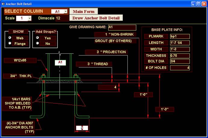
Select column from combo box, assign parameters, select scale, give the name for drawing and press button “Draw Anchor Bolt Detail”. If you need to draw anchor bolt with no hook just type 0 (zero) for the length of hook. In this form you have options for showing either flange or web of the column and whether or not to show straps.
You have at your disposal automatically updated report: “Nodes”.
This module gives you possibilities to:
· · · Make calculations using any formats of numbers;
· · · Solve triangles;
· · · Have at your disposal database of structural shapes (more than thousand shapes in registered copy of program) with fast search;
· · · Select and print W- shapes data;
· · · Use clipboard to transfer text or numbers in AutoCAD or other applications.
To launch module press button “Calcshapes” in main form
1. Calculator
In order to make calculations you have to enter numbers in field [1] using formats:
· · architectural (5’-4 11/16 or 12’-3 7/8 or 10’ etc.);
· · fractional (14 5/16 or 1 3/16 or 13/128 or 156/1793 etc.);
· · decimal (14.55 or 0.001 etc.)
After putting number in [1] press TAB key, put number in field [2], press TAB, type in combo box (yellow box between [1] and [2] – see picture) “+”or “-“or “/“or “x“ or “sqr“ (square root of number [1]) or “pow” ([1]^2), press TAB.

The “TOTAL” fields represent result of calculations in various formats. Decimal representation of result of calculation gets into clipboard of your computer and in the field “Clipboard”. Button “CLEAN” makes fields [1] and [2] equal 0.
2. Triangles
Fill out numbers in fields [1] and [2] ([1] must be less than [2]) and then press button “BEVEL”. Results: angle, hypotenuse of triangle and bevel.
3. Database of shapes
You can select shape in combo box named “Full name” by typing W8x31 or in combo box “Short name” type W831, or in “W-SHAPES” – just type 831 (last combo box – only for W-shapes search, this is the fastest way to select).
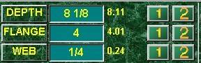
On pressing buttons “1” or “2” (see the picture below) shape data (depth, web etc.) get into calculator – fields [1] or [2] respectively
Example: define thickness of fill plate for the splice connection of columns W12x87 and W12x65.
· Select (or type) in [W-SHAPES] 1287, then press button “1” next to field [Depth];
· Select in [W-SHAPES] 1265 and press button “2” next to the field [Depth];
· Type “-“ in yellow field of Calculator, press TAB on keyboard;
· Enter number 2 in field [2], press TAB, type or select “/” and press “Enter”.
At the beginning a new job it is helpful to have printed shapes data. Press button “SELECT SHAPES” for opening form then select from the list W-shapes you would use in the job. Fill out the job name and press button “OPEN REPORT” for preview and print.
***************************************************************
If you decide to buy Quick Structural, you need to register your license. In main form press the button: “Register”. Follow instructions in opened form. Payment can be made on-line. Checks or money orders acceptable as well. For current price and conditions of payment follow the link:
http://www.nyacad.com/BuyOnLine.htm
====================================================================
If you have any questions or comments, please feel free to contact us via email alex@nyacad.com or visit our web site at: http://www.nyacad.com